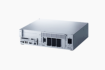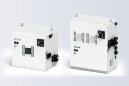
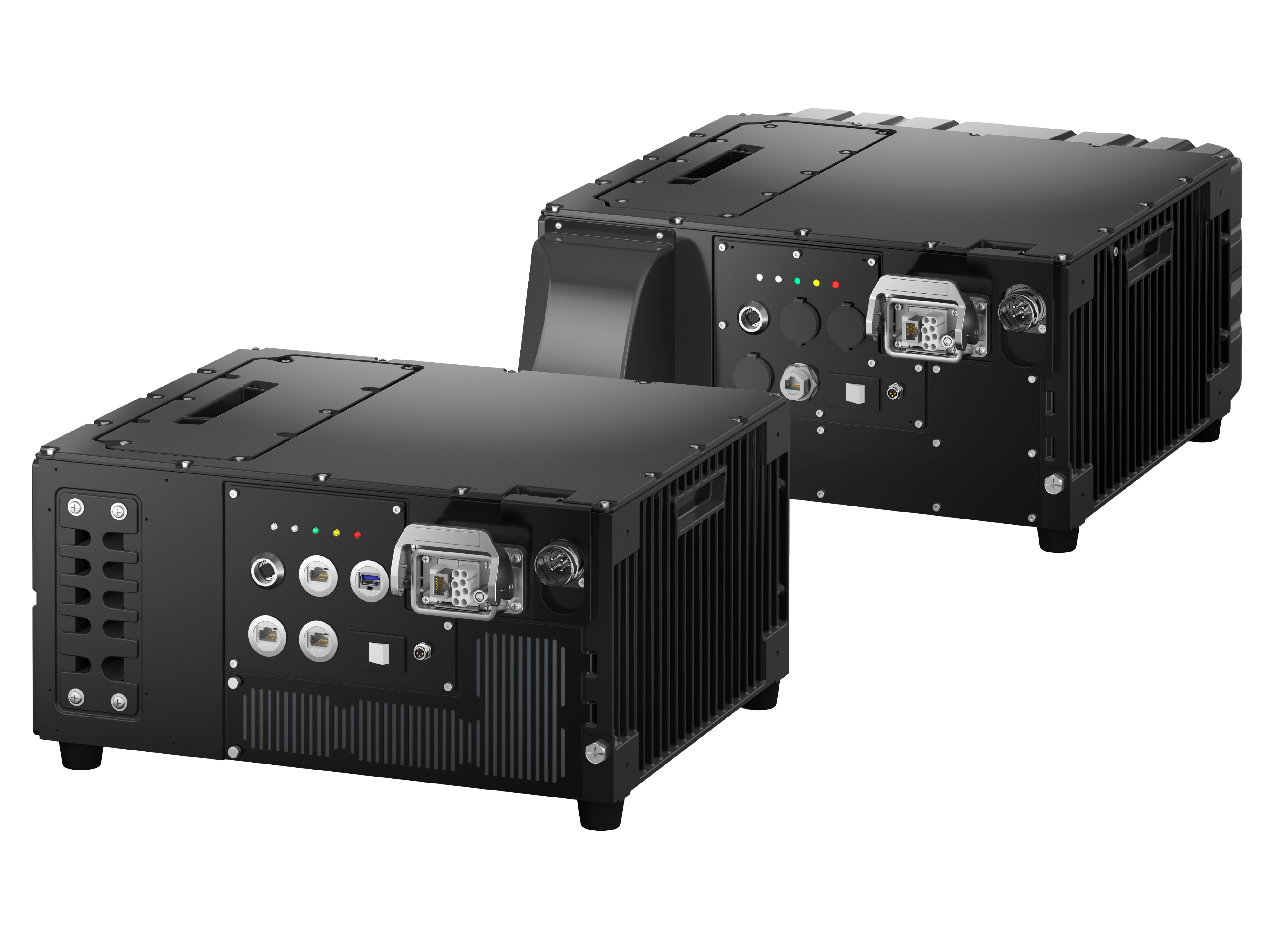
It is a new concept robot controller that can be provided by firmware. We provide the optimal robot system for each customer.
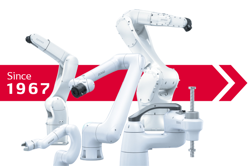
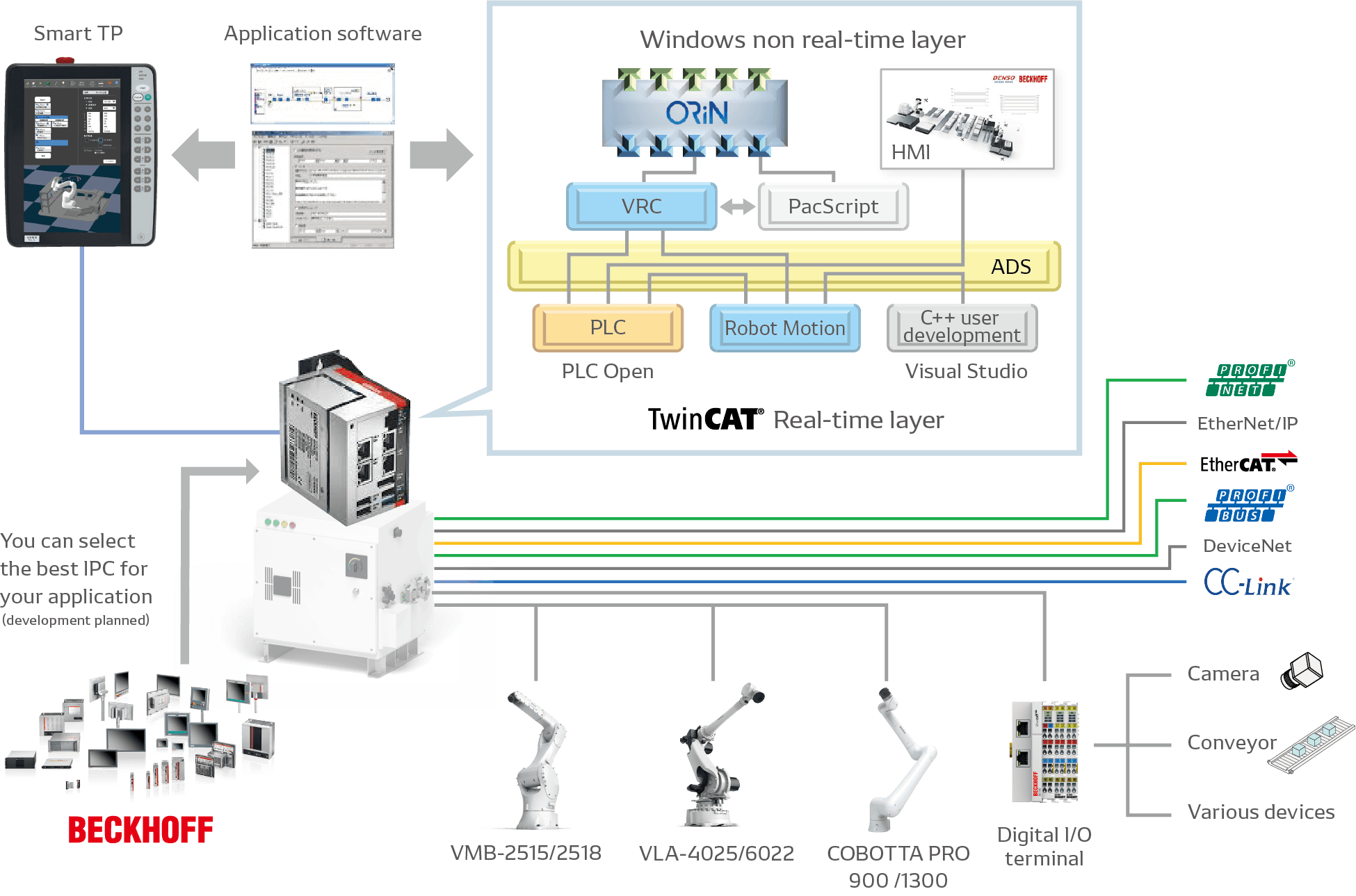
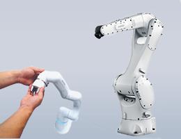
The RC9/CRC9 controller allows you to select the most suitable robot, peripheral equipment, and software for your application. While maintaining the RC8 development environment, new teaching devices and the application software “WINCAPS Plus” are provided for further simplification. These features deliver simplicity and peace of mind for everyone involved in robot start-up and operation.
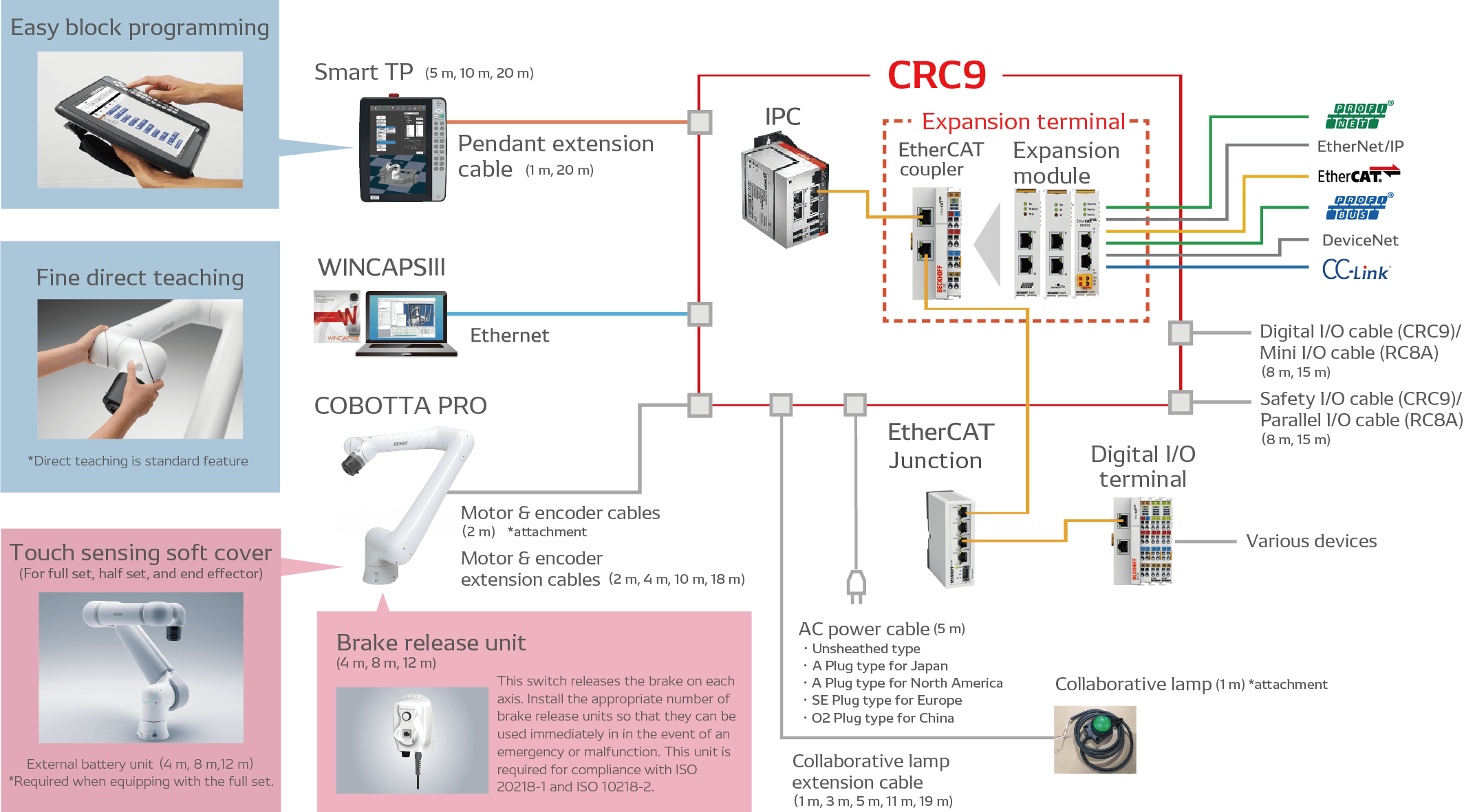
* CRC9 is a dedicated controller for COBOTTA PRO, which was developed based on RC9.
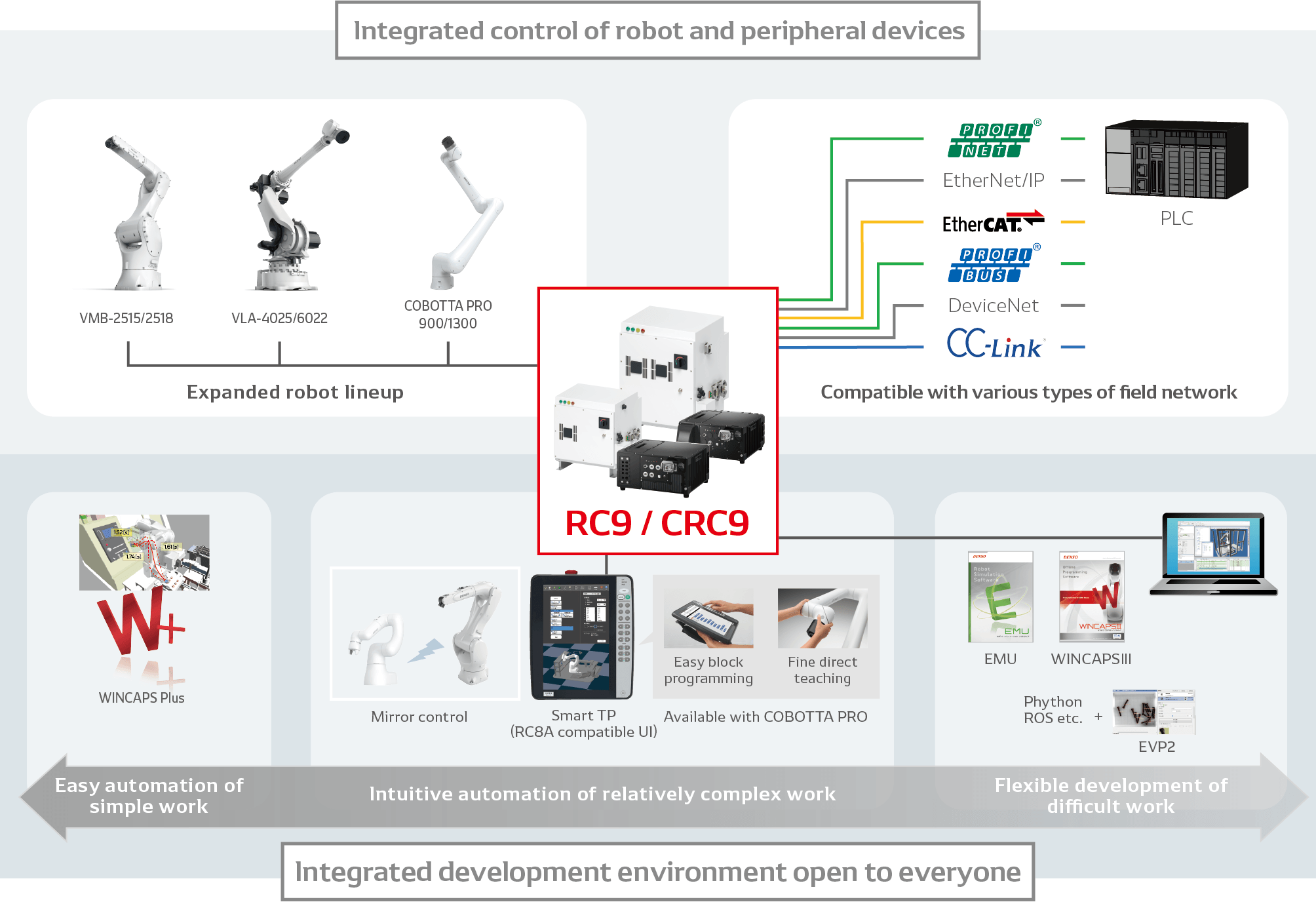
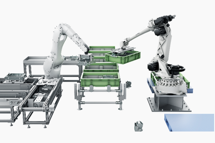
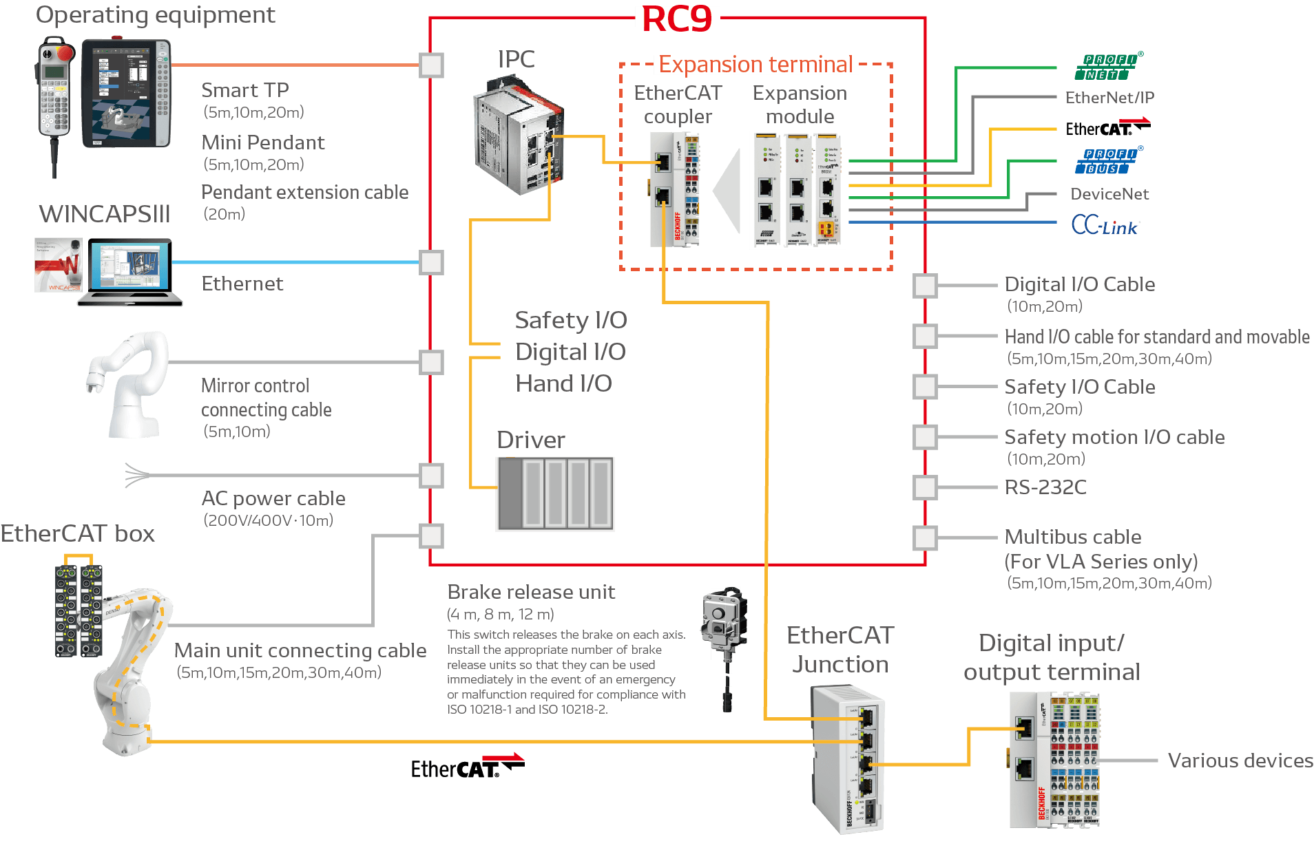
By combining selectivity for optimization according to the application; openness for integration of the user, system integrator, and manufacturer technologies; and Expandability for simple integration of the entire system, the RC9 controller achieves simple integrated facility control.
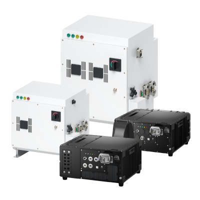
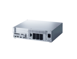
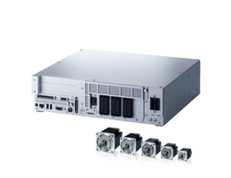
| Type | RC9M | RC9L | CRC9 | |
|---|---|---|---|---|
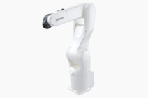
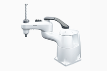
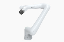
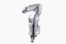
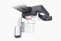
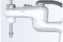
| Compatible robot | VMB-2515series | VLA-4025series | COBOTTA PRO 900 / COBOTTA PRO 1300 | |
 |
 |
 |
||
| Power supply | Power supply capacity | 4.5kVA | 10.0kVA | 1.0kVA |
| Input voltage range | 3-phase 200 V AC -10% to 230 V AC +10% | 3-phase 400 V AC -10% to 480 V AC + 10% | Single-phase 200 V AC -15% to 240 V AC +10% Single-phase 100 V AC -15% to 120 V AC +10% |
|
| Power supply frequency | 47~63Hz | |||
| Power cable length | 10m | 5m Select a type from 5 types. ・Unsheathed type ・A Plug type for Japan ・A Plug type for North America ・SE Plug type for Europe ・O2 Plug type for China |
||
| Number of control axes | 6 | |||
| Control method | PTP, GP 3-dimensional straight line, 3-dimensional arc | |||
| Language | PacScript (DENSO Robotics language) | PacScript (DENSO Robotics language), Easy Block Programming (Optional) | ||
| Teaching method | 1) Remote teaching 2) Numerical entry (MDI) | 1) Remote teaching 2) Numerical entry (MDI) 3) Direct Teaching 4) Fine Direct Teaching (Optional) |
||
| External signals | Digital I/O | System input: 8 pins / system output: 8 pins User input: 8 pins / user output: 8 pins |
System input: 8 pins / system output: 9 or 10 pins User input: 8 pins / user output: 7 or 8 pins |
|
| Hand I/O | User input: 12 pins User output: 12 pins |
User input: 6 pins User output: 6 pins (including Motor & encoder cable) |
- | |
| Safety I/O | System input: 6 pins / system output: 8 pins | User safety input: 16 pins User safety output: 16 pins External emergency stop input: 2 pins Enable auto input: 2 pins Protective stop input: 2 pins Enabling switch output: 2 pins Pendant emergency stop output: 2 pins STO monitor output: 2 pins |
||
| External communications |
Ethernet | Side of the robot controller: 1 line (GbE: Gigabit Ethernet) | Front panel of the robot controller: 2 lines (GbE: Gigabit Ethernet) (One line is used only for sending safety parameters.) | |
| EtherCAT | - | Front panel of the robot controller: 1 line | ||
| USB | Side of the robot controller: 1 line Inside of the robot controller (Robot Control IPC): 3 lines |
Front panel of the robot controller: 1 port Inside of the robot controller (robot control IPC): 2 ports |
||
| Optional expansions | 3 units (Two I/O terminals are regarded as one unit.) | |||
| Self-test function | Overrun, servo error, memory error, input error, short-circuit detection (user wiring), etc | |||
| Error display | External error output | |||
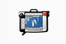
| Display of error codes on mini-pendant (option) | Display of error message and recovery method on Smart TP | |||
| Display of error messages and recovery methods on teaching pendant (option) | ||||
| Environmental conditions (during operation) | Temperature: o· C to 40° C; humidity: 20% to 90% RH (non-condensing) | Temperature: o· C to 50° C; humidity: 20% to 90% RH (non-condensing) | ||
| I/0 power supply | Uses external power supply | Supply 24 V DC ± l0% from external source | ||
| Uses internal power supply | 24 V DC ± 10% is supplied by the controller. | |||
| Safety-related control systems and performance | PL d, Cat. 3 | |||
| Overvoltage category (IEC 60664-1) |
Ⅲ | II | ||
| Electric shock protection class | I | - | ||
| Protection class | IP54 | IP20, IP54 | ||
| Pollution degree (IEC 60664-1) |
3 | IP20: 2*¹ IP54: 3 |
||
| Weight | Approx. 93kg | Approx. 104kg | IP20 : Approx. 15kg IP54 : Approx. 18kg |
|
| Outer dimensions | 600 (W) ×582 (D) ×690 (H) mm | 600 (W) ×582 (D) ×840 (H) mm | IP20: 420 (W) ×360 (D) ×200 (H) mm IP54: 420 (W) ×461 (D) ×200 (H) mm Screws included, rubber feet not included. |
|
| Applicable standards | ISO 10218-1:2011, ISO 13849-1:2015, IEC 60204-1:2016/A1:2021, EN 61000-6-7:2015 |
ISO 12100:2010, ISO 10218-1:2011, ISO 13849-1:2015, IEC 60204-1:2016/A1:2021, ISO/TS 15066:2016, ISO 13850:2015, IEC 61508-1:2010 series, IEC 61800-5-1:2022, IEC 61800-5-2:2016, EN 61000-6-7:2015, IEC 63000:2018, ANSI/RIA R15.06-2012, CAN/CSA-Z434-14 |
||
*¹ Pollution degree 2 environment is equivalent to home and office areas.
| EtherCAT cable | RJ45-RJ45, fixed: 0.5, 2, 5, 10, 20, 40 m | ||
| RJ45-RJ45, flexible (non-torsion): 0.5, 2, 5, 10, 20, 40 m | |||
| Cable for EtherCAT box | Power cable | M8-Open, flexible: 2, 10, 40 m | |
| M8-M8, flexible: 0.5, 2, 5, 10, 20, 40 m | |||
| 7/8”-Open, flexible (non-torsion): 2, 10, 40 m | |||
| 7/8”-7/8”, flexible (non-torsion): 0.5, 2, 5, 10, 20, 40 m | |||
| EtherCAT cable | M8-RJ45, flexible (non-torsion): 0.5, 2, 5, 10, 20, 40 m | ||
| M8-M8, flexible: 0.5, 2, 5, 10, 20, 40 m | |||
| Sensor cable for IO-Link | M12-Open, Class A, flexible: 2, 10, 40 m | ||
| M12-M12, Class A, flexible: 0.5, 2, 5, 10, 20, 40 m | |||
| M12-Open, Class B, flexible (non-torsion): 2, 10, 40 m | |||
| M12-M12, Class B, flexible (non-torsion): 0.5, 2, 5, 10, 20, 40 m | |||
| Sensor cable for DIO | M8-Open, flexible: 2, 10, 40 m | ||
| Extension Function (USB dongle / License certificate) |
TwinCAT3 PLC | ||
| TwinCAT3 PLC + HMI Web | |||
| Power supply | Power Transformer (VMB) (Built-in) | ||
| Power Transformer (VLA) (Built-in) | |||
| Field Network | EtherCAT junction | 3 ports, 4 ports, 8 ports | |
| EtherCAT bridge terminal | |||
| PROFINET RT controller terminal | |||
| PROFINET RT device terminal | |||
| EtherNet/IP master terminal | |||
| EtherNet/IP slave terminal | |||
| PROFIBUS master terminal | |||
| PROFIBUS slave terminal | |||
| DeviceNet master terminal | |||
| DeviceNet slave terminal | |||
| CC-Link slave terminal | |||
| Serial Transmission | RS232C 2ch terminal | ||
| RS422/RS485 2ch terminal | |||
| Digital input/output | Digital input terminal PNP, 8ch, 10us, IP20 | ||
| Digital input terminal PNP, 16ch, 3ms, IP20 | |||
| Digital output terminal PNP, 8ch, 0.5A, IP20 | |||
| Digital output terminal PNP, 16ch, 0.5A, IP20 | |||
| Digital input terminal NPN, 8ch, 10us, IP20 | |||
| Digital input terminal NPN, 16ch, 3ms, IP20 | |||
| Digital output terminal NPN, 8ch, 0.5A, IP20 | |||
| Digital output terminal NPN, 16ch, 0.5A, IP20 | |||
| EtherCAT box | DIO, PNP, 16ch, 3ms, IP67 | ||
| DIO, NPN, 16ch, 3ms, IP67 | |||
| IO-Link master, ClassA, IP67 | 4 ports, 8 ports | ||
| IO-Link master, ClassB, IP67 | 4 ports, 8 ports | ||
| Protection plugs M8, 50pcs for DIO | |||
| Protection plugs M12, 50pcs for IO-Link | |||
| Other | EtherCAT coupler terminal + Bus end cap set (Built-in) | ||
| EtherCAT coupler terminal (Single) | |||
| Bus end cap (Singile) | |||
| EtherCAT extension terminal | |||
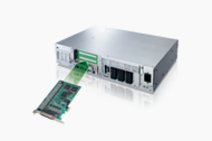
| Ethernet expansion module (Built-in) | |||
| AC power cable (5 m) *Select one. |
Unsheathed type | ||
| A Plug type for Japan | |||
| A Plug type for North America | |||
| SE Plug type for Europe | |||
| O2 Plug type for China | |||
| EtherCAT cable | RJ45-RJ45, fixed: 0.5, 2, 5, 10, 20, 40 m | ||
| RJ45-RJ45, flexible (non-torsion): 0.5, 2, 5, 10, 20, 40 m | |||
| Cable for EtherCAT box | Power cable | M8-Open, flexible: 2, 10, 40 m | |
| M8-M8, flexible: 0.5, 2, 5, 10, 20, 40 m | |||
| 7/8”-Open, flexible (non-torsion): 2, 10, 40 m | |||
| 7/8”-7/8”, flexible (non-torsion): 0.5, 2, 5, 10, 20, 40 m | |||
| EtherCAT cable | M8-RJ45, flexible (non-torsion): 0.5, 2, 5, 10, 20, 40 m | ||
| M8-M8, flexible: 0.5, 2, 5, 10, 20, 40 m | |||
| Sensor cable for IO-Link | M12-Open, Class A, flexible: 2, 10, 40 m | ||
| M12-M12, Class A, flexible: 0.5, 2, 5, 10, 20, 40 m | |||
| M12-Open, Class B, flexible (non-torsion): 2, 10, 40 m | |||
| M12-M12, Class B, flexible (non-torsion): 0.5, 2, 5, 10, 20, 40 m | |||
| Sensor cable for DIO | M8-Open, flexible: 2, 10, 40 m | ||
| Extension Function (USB dongle / License certificate) |
TwinCAT3 PLC | ||
| TwinCAT3 PLC + HMI Web | |||
| Field Network | EtherCAT junction | 3 ports, 4 ports, 8 ports | |
| EtherCAT bridge terminal | |||
| PROFINET RT controller terminal | |||
| PROFINET RT device terminal | |||
| EtherNet/IP master terminal | |||
| EtherNet/IP slave terminal | |||
| PROFIBUS master terminal | |||
| PROFIBUS slave terminal | |||
| DeviceNet master terminal | |||
| DeviceNet slave terminal | |||
| CC-Link slave terminal | |||
| Serial Transmission | RS232C 2ch terminal | ||
| RS422/RS485 2ch terminal | |||
| Digital input/output | Digital input terminal PNP, 8ch, 10us, IP20 | ||
| Digital input terminal PNP, 16ch, 3ms, IP20 | |||
| Digital output terminal PNP, 8ch, 0.5A, IP20 | |||
| Digital output terminal PNP, 16ch, 0.5A, IP20 | |||
| Digital input terminal NPN, 8ch, 10us, IP20 | |||
| Digital input terminal NPN, 16ch, 3ms, IP20 | |||
| Digital output terminal NPN, 8ch, 0.5A, IP20 | |||
| Digital output terminal NPN, 16ch, 0.5A, IP20 | |||
| EtherCAT box | DIO, PNP, 16ch, 3ms, IP67 | ||
| DIO, NPN, 16ch, 3ms, IP67 | |||
| IO-Link master, ClassA, IP67 | 4 ports, 8 ports | ||
| IO-Link master, ClassB, IP67 | 4 ports, 8 ports | ||
| Protection plugs M8, 50pcs for DIO | |||
| Protection plugs M12, 50pcs for IO-Link | |||
| Other | EtherCAT coupler terminal + Bus end cap set (Built-in) | ||
| EtherCAT coupler terminal (Single) | |||
| Bus end cap (Singile) | |||
| EtherCAT extension terminal | |||
| Ethernet expansion module (Built-in) | |||
※EtherCAT® is a registered trademark and patented technology, licensed by Beckhoff Automation GmbH, Germany.
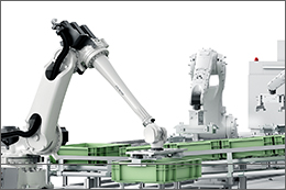
Enables common use of the motion area while achieving both safety and high productivity.
* Scheduled for release in 2024
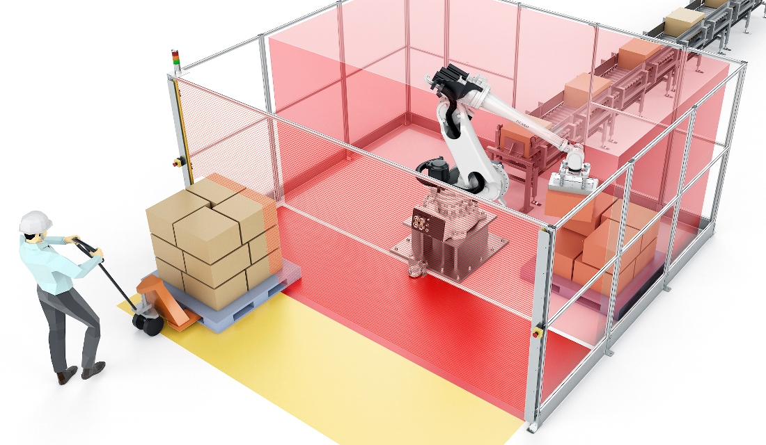
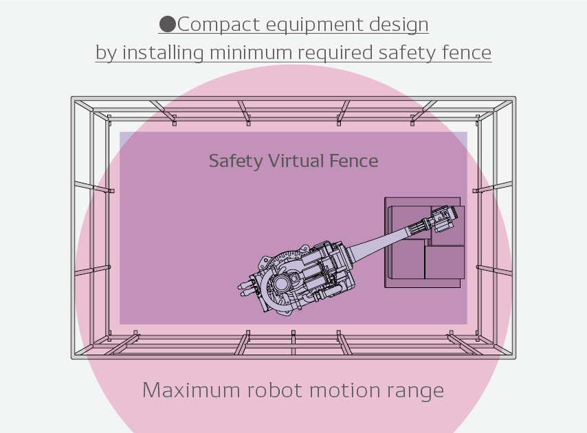
Uses the safety virtual fence function to monitor that the robot does not move outside the set motion range.
■ Benefits
・Enables installation of minimum required safety fence for compact equipment design
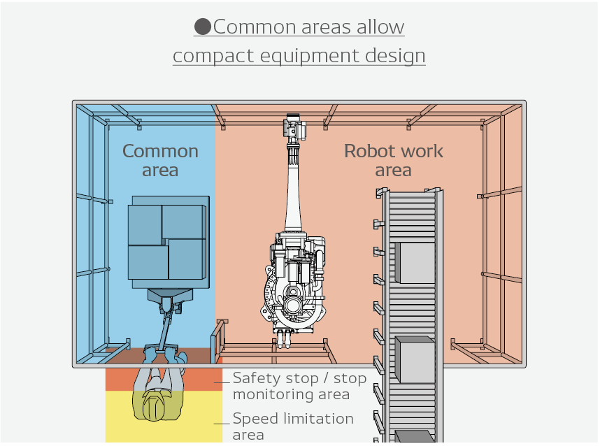
・Enables installation of common work areas for workers and robots using sensors*
Uses the monitored-speed function to monitor that the robot does not exceed the set operating speed.
■ Benefits
・Reduces the speed to a safe level when a sensor* detects an approaching worker
Uses the Robot Stop monitoring function to monitor that the robot remains stationary after having stopped with its motor ON.
■ Benefits
・Robot stops with the motor ON when a sensor* detects the entry and presence of an operator inside the stop area
・Enables fast restarting of the program by maintaining the standstill status
| Name | Description |
|---|---|
| Emergency Stop Function | Decelerates the robot until it stops, and then turns OFF the motor. The current program will be Reset-Stopped. |
| Protective Stop Function | This function is to be connected to a signal from a safeguard or the like installed in the robot system/cell and stop the robot in response to the input signal. |
| Monitored-Speed Function | Monitors the robot speed to confirm if it does not exceed the specified speed. |
| Axis Limiting Function | Monitors the robot axes to confirm if they are not out of the specified motion range. |
| Monitored Standstill Function | Monitors the robot to confirm if it remains stationary after having stopped with its motor ON. |
| Safety Virtual Fence Function | Monitors the robot to confirm if it does not go beyond the specified motion range. |

If you have not registered
The services on this member site are available only for registered customers.